

1. Introduction
2. Numerical Methods
2.1 Numerical model
2.2 Reaction mechanism
2.3 Design modification
3. Results and discussion
3.1 Effect of air fuel ratio
3.2 Effect of air slit area
4. Conclusion
1. Introduction
Gas turbines for power generation are widely used in the past few decades. Because they are fueled by liquid or gaseous hydrocarbon fuels, so a large number of pollutant gases and green-house gases are emitted from the combustor. In the 1970s, emission controls were first introduced and the pollutant of primary concern was NOX [1]. Accordingly, the NOX emission becomes one of important design factors for burner design and manufacturing of gas turbines. In order to meet the increasingly stringent regulations and guidelines of pollutant emissions, various technologies and concepts have been adopted in stationary gas turbines. For example, they are lean premixed (LPM) and catalytic combustion [2-3]. And LPM combustion became the standard technology in may power-generation applications because it reduces NOX emissions greatly while maintaining CO emission levels that meet the standard [4].
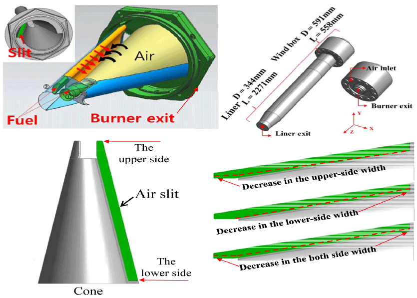
In order to achieve the purpose of lean premixed combustion, the gas turbine produced by Alstom company adopted the EV (EnVironmental) burner [2]. As shown in Fig. 1, air is injected into the burner with swirl flow through air slit while fuel is injected from cross direction and mixed with air. The advantage of this specific geometry is that the burner provides uniform mixing of fuel and air, which contributes to reduction of NOX emission and increase in flame stability for fuel lean condition [5]. Several studies devoted to NOX reduction through enhancement of air and fuel mixing were carried out [6-7]. In the previous study, the effect on mixing was investigated by changing the diameter and position of side fuel holes and adding a fuel lance injection to the burner [8-9]. For the EV burner, there is still room for improvement in the internal mixing of the burner. And, study on the degree of mixing is of great significance for reducing the NOX emission in a combustor.
In this regard, this study is focused on two variables related to the mixing characteristics of EV burner. The first one is air fuel ratio (A/F ratio), and the second is the area of the air slit that has not been considered before. The relationship between two parameters and NOX emission is studied by numerical simulation. The research results provide a reference for the actual production and manufacture of gas turbines in reducing pollutant emissions.
2. Numerical Methods
2.1 Numerical model
As shown in Fig. 1, the EV burner is installed on the top of the model combustor. Detailed information on its geometry can be found in Ref. 10. Although premixed flames are formed by the EV burner, air and fuel are injected separately at the initial stage and they are mixed in the cone part of the burner. Fuel is injected through the side holes in a cross direction and various arrangement and combination can be checked in the previous paper [10]. The air slit located on both sides of EV burner is one of the research targets in the present study.
In this analysis, continuity, momentum, energy, and species transport equations are solved to resolve a reacting flow field. The three-dimensional governing equations can be found in the literature and are omitted here [10]. The realizable k-ε model is adopted to simulate the turbulent flow and finite-rate/eddy dissipation model is used for consideration of turbulent combustion accompanying chemical reactions. For spatial discretization of the partial differential equations, the 2nd-order upwind scheme is employed. The number of hybrid mesh grids depends on the geometry of each case is around 3,500,000. This numerical model was established in the previous study and validated with experimental results [10]. The results showed that this model can accurately simulate the qualitative trend of pollutant emission in the combustor. All equations are solved by using a general purpose CFD code, FLUENT [11]. The calculation was performed on a desktop with Intel(R) Core(TM) i7-4930K CPU. It took about 50 hours for steady state calculation of a single EV burner case.
2.2 Reaction mechanism
Methane (CH4) is selected as a fuel in a model combustor of a gas turbine. To simulate chemical reaction of methane reasonably and cost-effectively, the following 2-step global reaction is adopted [12],
The reaction rate of each reaction can be expressed in the Arrhenius form,
where A is a pre-exponential factor, n temperature index, Ea activation energy, and a and b are concentration indices. Values of all the parameters are listed in Table 1.
Table 1.
Parameters for chemical reaction rates of two reaction steps
| A | n | Ea/R[K] | [A] | [B] | a | b |
| 4.56E11 | 0 | 20087 | CH4 | O2 | 0.2 | 1.3 |
| 3.16E12 | 0 | 24417 | CO | O2 | 1.5 | 0.25 |
In order to predict NOX emission, thermal NOX generated by Zeldovich mechanism, NOX formation from prompt NO mechanism(or Fenimore mechanism), and N2O intermediates mechanism are all taken into consideration [12,13,14,15]. The thermal NO can be calculated by the following steps with the rate equation of Eq.(7):
Rate constants of each step are listed in Table 2. The prompt NO mechanism can be simulated with the following reactions,
where activation energy, Ea, has the value of 251,151 j/mol and the molar concentration of oxygen in the flame is powered by the oxygen reaction order, a. And, for the condition of fuel lean (Φ<0.8) and low temperature, N2O intermediates mechanisms are also important and considered in this study [13]. Here, NOX is composed of two species: NO and N2O.
Table 2.
Reaction rate of reactions for thermal NO formation
| Forward reaction [m3/mol-s] | Backward reaction [m3/mol-s] | ||
| kf,1 | 1.8*108e(-38370/T) | kr,1 | 3.8*107e(-425/T) |
| kf,2 | 1.8*104Te(-4580/T) | kr,2 | 3.81*103Te(-20820/T) |
| kf,3 | 7.1*107e(-450/T) | kr,3 | 1.7*108e(-24560/T) |
2.3 Design modification
Two factors, air fuel ratio and air slit area, are considered to investigate their effects on NOX emission. The first factor is air fuel ratio(A/F ratio) and adjusted by decreasing fuel mass flow rate from 0.0158 kg/s to 0.0129 kg/s while air mass flow rate is fixed at 0.5 kg/s. Six A/F ratios are chosen and they are 31.7, 32.2, 33.7, 34.3, 35.7 and 38.7. And, 35.7 is the A/F ratio for the actual operating condition of the gas turbine that can be found in Table 3. As a function of A/F ratio, the mixing characteristics and temperature inside the burner and the model combustor are analyzed. And, the second factor is the area reduction of air slit of EV burner. Air slit area is changed by decreasing the width of slit as shown in Fig. 1. Three kinds of methods are adopted to change the width: decrease in the width at the upper side only, at the lower side only, and at the both sides. When the width is reduced only at the upper or lower side, decrement is from 1 mm to 4 mm with the step of 1 mm. For width reduction at both sides, only 3 cases from 1 mm to 3 mm are considered. The width and area reduction of air slit is summarized in Table 4.
3. Results and discussion
3.1 Effect of air fuel ratio
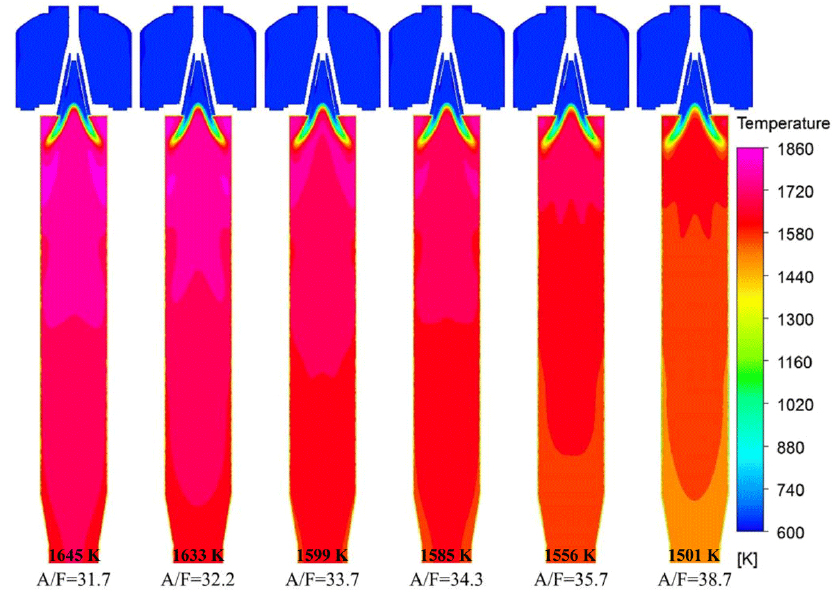
As aforementioned, six cases of A/F ratio are simulated. A/F ratio for operating condition of a gas turbine is 35.7 (Φ=0.48). A/F ratios in the six cases increase from 31.7 (Φ=0.54) to 38.7 (Φ=0.44) by decreasing fuel mass flow rate with air flow rate fixed. From adiabatic flame temperature of methane as a function of equivalence ratio, it is known that when the equivalence ratio is less than 1, flame temperature decreases as the equivalence ratio becomes smaller [13]. Therefore, it is found in Fig. 2 that temperature in the combustor with A/F ratio of 31.7 (Φ=0.54) is the highest. And, temperature decreases as A/F ratio increases. From 31.7 to 38.7, the combustor exit temperature decreases by 144 K. In addition, the flame length at A/F ratio of 38.7 is longer than that of 31.7. The phenomenon is mainly due to the fact that the reaction rate is improved as flame temperature increases. Accordingly, the flame length grow longer at lower temperature.
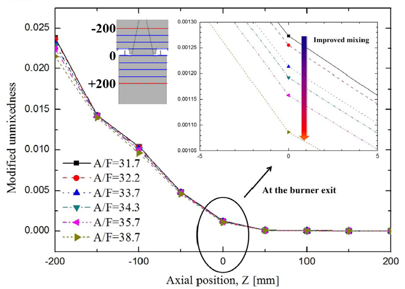
In this study, uniform mixing of fuel and air is evaluated by a parameter, modified unmixedness, Um, defined as
where f denotes fuel mass fraction and faver is its average over a cross-sectional area. The smaller modified unmixedness means more uniform mixing of fuel and air. Its original form was modified in our previous study [10].
The modified unmixedness is calculated at 9 locations near the burner exit with an interval of 50 mm as shown in Fig. 3. The unmixedness decreases in the axial direction from upstream to downstream. It means that mixing proceeds as the mixture flows downstream. The burner exit, where the axial coordinate, Z, is equal to 0 mm, is selected as a monitoring position because the main flame starts to generate near this position. When the unmixedness at the burner exit is magnified, it is seen than the unmixedness decreases slightly with A/F ratio, which means that the mixing is enhanced more at higher A/F ratio.
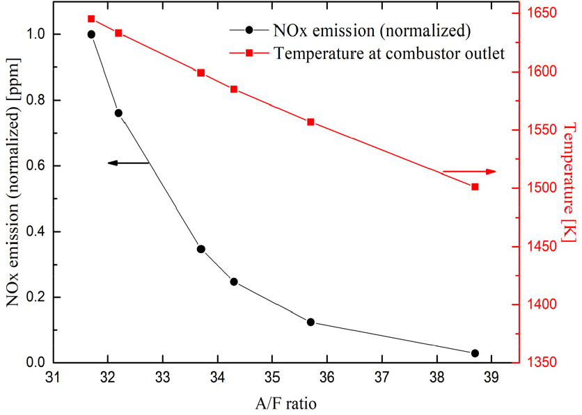
NOX emission and temperature at the burner exit in each case are shown in Fig. 4. The NOX emission value at A/F ratio of 31.7 is 2.265 ppm. NOX emission is normalized by this maximum value. It is found that as A/F ratio increases, temperature decreases linearly because of the reduced equivalence ratio for fuel lean condition. It leads to decrease in the amount of thermal NOX generated by Zeldovich mechanism. And, thereby, total NOX emission is reduced, but non-linearly. Enhanced mixing at higher A/F ratio also contributes to reduction of NOX emission. But it is worth noting that temperature decreases linearly, while NOX emission does nonlinearly. This nonlinearity would be the combined effect of enhanced mixing and temperature decrease.
3.2 Effect of air slit area
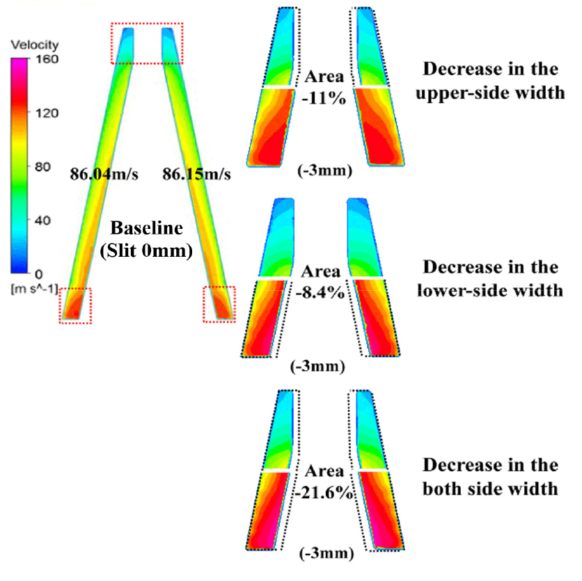
Fig. 5 illustrates the air slit of EV burner and where the area of air slit is reduced by three methods. The baseline means the original air slit without design modification. Width decreases by 3 mm on the upper, lower, and both sides and thereby, area is reduced by 11%, 8.4%, and 21.6%, respectively. As aforementioned in the previous section and listed in Table 4, eleven cases are simulated.
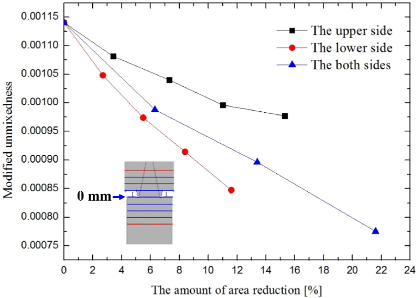
In this simulation, air and fuel flow rates are fixed for the operating condition as shown in Table 3. Accordingly, temperature inside the combustor does not show large discrepancy. It can be considered that the temperature distribution is almost the same. Therefore, the effect of temperature on NOX emission is negligible here. Because area of air slit is reduced, air velocity will be increased. In Fig. 6, modified unmixedness in each case calculated at the burner exit (at axial coordinate = 0 mm) is shown. Because of increases in air velocity, mixing is enhanced between fuel and air. This can be confirmed by decrease in unmixedness with area reduction. It is worth noting that unmixedness is the smallest when area is reduced only on the lower side, which indicates that mixing is enhanced more by air-slit design change of the lower side.
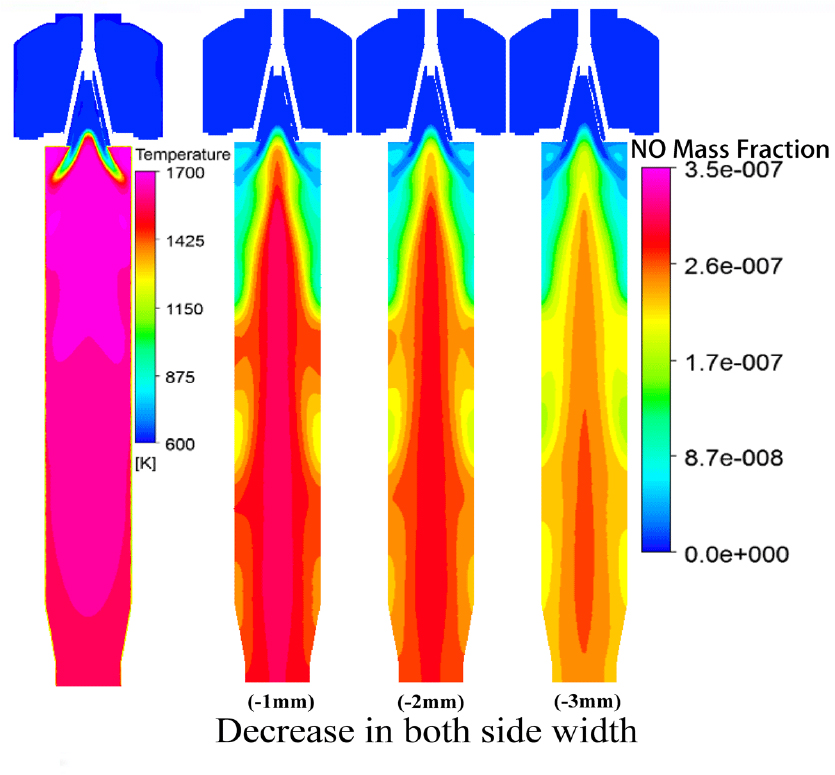
Temperature and NOX emission fields in the cases, where air slit width is reduced by 1, 2, and 3 mm at both sides, are shown in Fig. 7. Temperature fields are shown in the left of the figure and similar to each other not shown here. On the other hand, NOX emission is reduced appreciably as the width is reduced more.
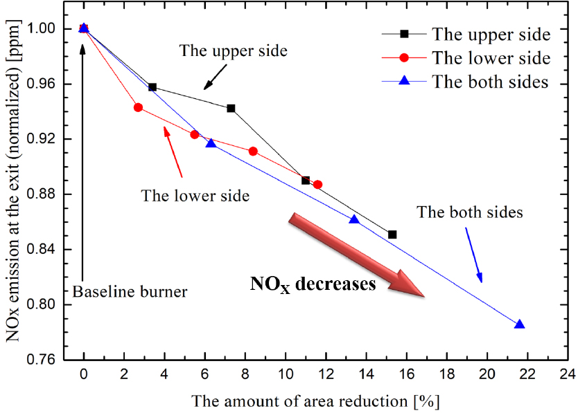
NOX emission is shown as a function of area reduction of air slit in Fig. 8. When area reduction is relatively small below 6%, area reducton applied on lower side makes lowest emission. However, at larger reduction than 6%, NOX emission becomes similar to each other in terms of quantity and tendency. Moreover, when area reduction exceeds a critical value around 10%, NOX emission decreases linearly irrespective of its position. For example, NOX emission is reduced by 21% compared with that from the baseline burner when area of air slit is reduced by 21.6%.
4. Conclusion
Effects of A/F ratio and reduction of air slit area on NOX emission have been investigated numerically with EV burner. When A/F ratio increases under fuel lean condition, temperature decreases and mixing of fuel and air is enhanced. This reduces NOX emission because it depend strongly on temperature and the mixing characteristics. Similarly, air velocity is increased by reducing the area of air slit, resulting in enhanced uniform mixing. Then, NOX emission decreases almost linearly as a function of air slit area reduction irrespective of area-reduction position.
The parametric studies in the present simulation will provide useful reference information on design modification and manufacture of a gas turbine combustor in the future. Several works relevant to NOX reduction by design change will be considered as the future work.
